
GZW80/165
Mining Intrinsically Safe Vibration Temperature Sensor
Category:
Our company designs and manufactures the GZW80/165 intrinsically safe mining-type vibration-temperature sensor (hereinafter referred to as the sensor), a dual-function product integrating both vibration and temperature measurements. It boasts outstanding features such as wide frequency response, high precision, strong anti-interference capability, excellent air-tightness, and long service life—making it the ideal matching product for vibration-temperature signal measurement and monitoring systems in applications requiring explosion-proof safety in mining environments. This product is specifically designed for measuring temperature as well as dynamic vibration acceleration.
Contact:
Design characteristics

· Altitude does not exceed 2000 meters.
· Ambient temperature: 0°C to +40°C
· Relative humidity of surrounding air: Not more than 95% (+25°C)
· Atmospheric pressure: 80 kPa to 106 kPa
· In hazardous areas where explosive mixtures of methane and coal dust are present
· Locations free of steam or corrosive gases that could damage metals and insulating materials
· A place with no dripping water
Product Advantages

· Integrated vibration and temperature dual functionality
· Wide frequency response, high precision
· Strong anti-interference capability and excellent airtightness
· Long service life
· Features explosion-proof functionality
Product Parameters
Electrical Performance Parameters
| Specification List | Test conditions: 25°C, 24Vdc, 4mA @ 160Hz | ||
| Parameter List | Specifications | Unit | |
| Vibration Performance | |||
| Measurement Range | 80 | g | |
| Output signal | 0–8000 | mV | |
| Vibration Measurement Error | ±8 | % True Value | |
| Temperature sensor parameters | |||
| Temperature measurement range | -40~125 | °C | |
| 0℃ Output Voltage | 500 | mV | |
| Sensitivity | 10 | mV/°C | |
| Temperature measurement error | ±5 | °C | |
| Output voltage range | 100–1750 | mV | |
| Electrical Characteristics | |||
| Stimulus voltage | 18–25 (Type 24) | Vdc | |
| Constant current source current | 2–10 (Type 4) | mA | |
| Bias voltage | 12 ± 2 | Vdc | |
| Output impedance | <100 | Ω | |
| Insulation impedance of the enclosure to energized circuits (@100Vdc) | >100 | MΩ | |
| Power-frequency withstand voltage (enclosure vs. energized circuit) | 1000 | Vacuum | |
| Broadband Noise (RMS) | ≤100 | μV | |
| Work environment | |||
| Operating Temperature Range | 0–40 | °C | |
| Pushing the Limits | 5000 | g | |
| Protection Level | IP67 |
| |
| Material Parameters | |||
| Sealing Method | Laser Welding |
| |
| Housing material | 316L Stainless Steel |
| |
| Sensitive Materials and Methods | Piezoelectric Ceramic Shear |
| |
| Electrical Output Method | 3-pin MIL-C-5015 |
| |
| Shielding and Isolation | Internal shielding, isolation |
| |
| Weight | 85 | gram | |
| Attachment | |||
| Adapter Bolt | 1/4-28 to M6 |
| |
Transportation Conditions
· Temperature: -40°C to +60°C;
· Humidity: 95% (+40℃);
· Vibration: 50 m/s 2;
· Impact: 500 m/s 2。
Installation Techniques and Electrical Connection Technologies
1 Sensor Body Installation
When using, first install the sensor. Select an appropriate measurement point on the device under test; at this location, there should be a smooth, flat surface with a diameter of at least φ24 to facilitate sensor installation. To ensure accurate vibration acceleration data and ease of use, the sensor must be securely mounted in the correct sensitive direction. Follow the recommended sequence below for proper tightening and installation.
1.1 Screw Installation Method
The bottom surface of the sensor should remain clean and smooth. Ideally, apply a thin layer of grease or wax oil between the sensor and the surface of the object being measured to enhance contact stiffness, then securely fasten it using the specified screws to achieve the sensor's calibrated frequency response characteristics.
Screw installation: A recommended installation torque is 3 Nm.
1.2 Adhesive Installation Method
When drilling into the test object is not permitted, equipment owners may use adhesives approved for this purpose, such as "502" superglue, Loctite "454," or other fast-drying glues, as well as alternatives like epoxy resin adhesives or double-sided adhesive tapes. However, adhesive mounting can slightly affect the sensor's frequency and amplitude characteristics, sometimes leading to measurement errors that are unacceptable. Additionally, adhesive installation is relatively sensitive to temperature changes, so careful selection should be made based on the specific conditions of the project.
1.3 Magnetic Suction Base Method
The method of installing the magnetic base can lead to a reduction in the upper limit of the vibration accelerometer's frequency response, as well as abnormal low-frequency performance. Therefore, it should be used with caution. When this installation method is employed, the measurement range tends to become more limited, and the magnetic attraction force is significantly affected by temperature—once a certain temperature threshold is reached, the magnet's magnetic capability rapidly degrades. Please be aware of these factors and choose carefully.
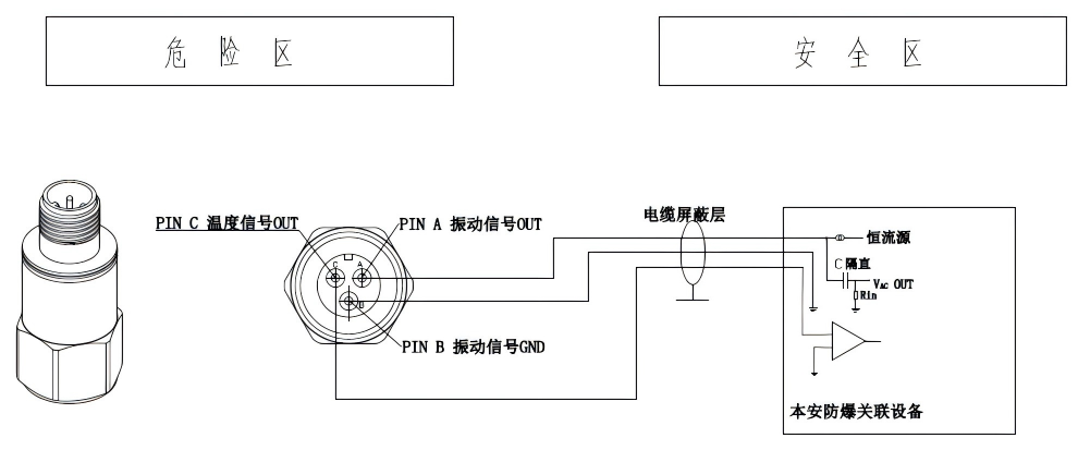
2 Electrical Connection Technology
This product features a two-wire IC circuit for its vibration section; therefore, it must be powered by a constant-current source. Directly connecting it to a DC power supply or using any other method of power supply is strictly prohibited, as this could easily damage the internal components and result in no output. The correct electrical connection is illustrated in the diagram below:
3 Cable Connection Technology
The selection of cables should comply with relevant standard specifications. In harsh environments characterized by high temperatures, high humidity, and exposure to acids, alkalis, or salt spray, cable assemblies meeting the appropriate protection ratings must be chosen. If necessary, protective flexible sealants should be used to fill any gaps, effectively preventing moisture intrusion as well as isolating against acidic, alkaline, and salt-spray effects. After completing the electrical connections, the cables should be securely fixed as close as possible to the sensor end. Whenever feasible, sensors should be positioned away from areas with strong acids or strong bases, minimizing the risk of contamination that could compromise the electrical contacts or degrade the overall performance of the electrical connections.
The maximum cable length for connecting the sensor to its associated equipment is 100 meters. However, excessively increasing the connection length may lead to a risk of attenuation in the high-frequency components of the vibration signal, as well as greater errors in temperature detection and increased interference signals.
Cables should prioritize products that meet the following specifications: cable cross-sectional area ≥ 0.5 mm² 2 ; Distributed capacitance is no more than 0.1 μF/km; line resistance is no more than 50 Ω/km.
Material Download
Recommended products

SL1000AT-10-LF
SL1000AT-80
SL3000-X
SL4000-X
Leave a message
We will contact you as soon as we receive your information and give you a surprise.
Service Hotline
+86 27-6349 9950
Contact Information
Email: administrator@hbicc.com
Address: No. 6, Fozulingle Third Road, East Lake High-tech Development Zone, Wuhan, Hubei Province