
Case Studies on the Application Effects of Equipment Online Monitoring and Fault Diagnosis Systems (Part 2)
Release time:2025-09-22
Case 1: Conveyor Belt - Coupling Failure
1. Sensor arrangement at measurement points
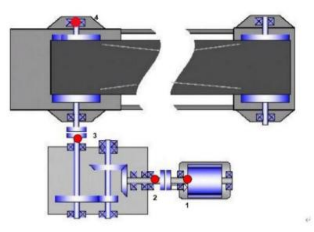
Equipment Name and Information
|
Measurement point
|
Measurement point location
|
Installation Direction
|
Sensor Type
|
23.04 Belt Conveyor
|
1
|
Motor drive end
|
Vertical
|
Three-in-one sensor
|
2
|
Gearbox input end
|
Vertical
|
Three-in-one sensor
|
|
3
|
Bearing housing at the input end of the head rotor
|
Horizontal
|
Three-in-one sensor
|
|
4
|
Bearing housing at the output end of the head rotor
|
Horizontal
|
Three-in-one sensor
|
2. Platform Failure Analysis
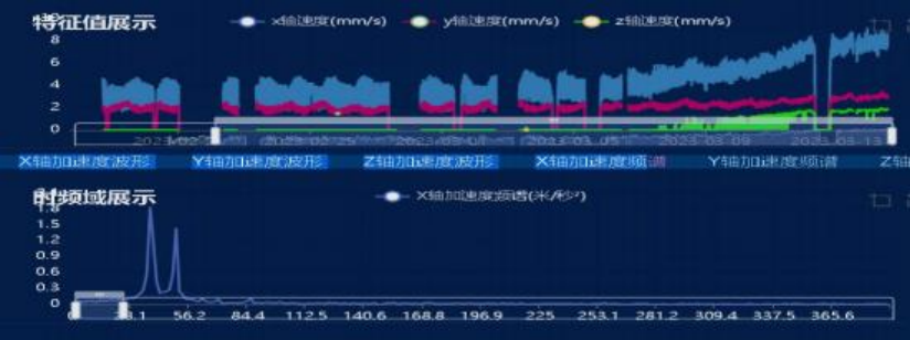
The trend of feature values at the motor drive end is as follows: it can be observed that both the acceleration and velocity feature values show a clear upward trend. A detailed waveform analysis will be conducted specifically for the motor drive end.
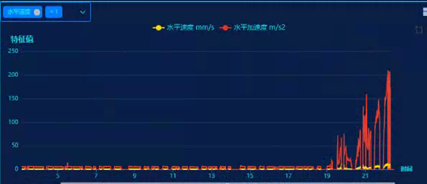
Motor Drive End Trend Chart
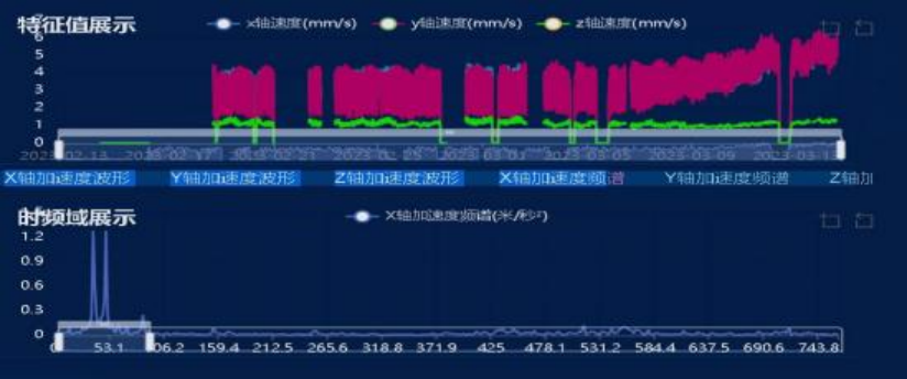
Comparing the spectrograms before and after the change in eigenvalues reveals that the primary spectral changes involve high-frequency components, with a significant increase in energy at the lower end of the spectrum. Additionally, distinct sidebands are evident in the spectrum, primarily spaced at 141.6 Hz. When performing envelope demodulation analysis on the 2300–6000 Hz range, the main frequency components in the envelope spectrum are 141 Hz and 65.6 Hz, neither of which corresponds to the expected bearing characteristic frequencies. Given the noticeable increase in vibration levels and the accompanying rise in background noise, it is recommended to verify the bearing information promptly. Furthermore, considering the possibility of loosening-related faults, an on-site inspection of both the bearings and the coupling condition is strongly advised.
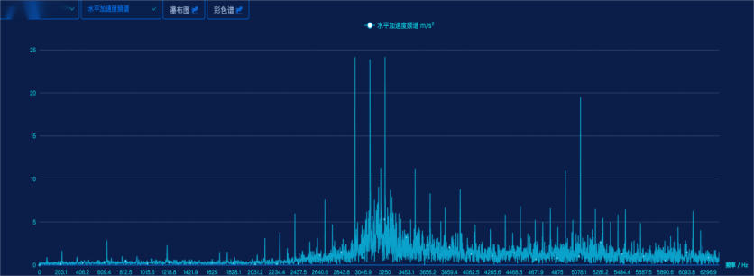
Vibration Acceleration Spectrum at the Motor Drive End
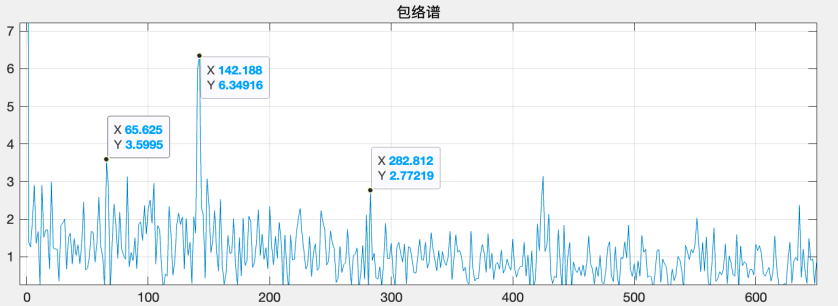
Vibration Acceleration Envelope Spectrum at the Motor Drive End
3. Diagnosis Conclusion and Recommendations
After systematic analysis and diagnosis: The vibration trend at the motor drive-end measurement point has明显 increased, with acceleration rising sharply from 5 m/s² to 200 m/s². Spectral analysis reveals a significant boost in high-frequency energy, accompanied by prominent sideband components. This suggests a possible bearing failure or coupling issue. It is recommended to verify the situation on-site and schedule a shutdown for thorough inspection.
4. User Maintenance Confirmation
After receiving the notification, the customer conducted an on-site inspection and reported that the coupling exhibited abnormalities. The increased vibration was found to be caused by excessive deformation of the elastic梅花 (plum blossom) pad, which subsequently led to the decision to replace the coupling with a new one. Following the replacement, the vibration levels dropped significantly, returning to normal. Additionally, the high-frequency energy above 2800 Hz virtually disappeared from the spectrum, while the main peak now appeared prominently around 2100 Hz.
Vibration Trend at the Motor Drive End
Vibration Acceleration Spectrum at the Motor Drive End
Case Two: Fan-Coupling Failure
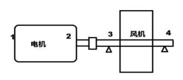
1. Sensor arrangement at measurement points
Equipment Name and Information
|
Measurement point
|
Measurement point location
|
Installation Direction
|
Sensor Type
|
Raw Material Grinding Circulation Fan
|
1
|
Motor free end
|
Vertical
|
Three-in-one sensor
|
2
|
Motor drive end
|
Vertical
|
Three-in-one sensor
|
|
3
|
Fan drive-side bearing
|
Vertical
|
Three-in-one sensor
|
|
4
|
Fan free-side bearing
|
Vertical
|
Three-in-one sensor
|
2. Platform Failure Analysis
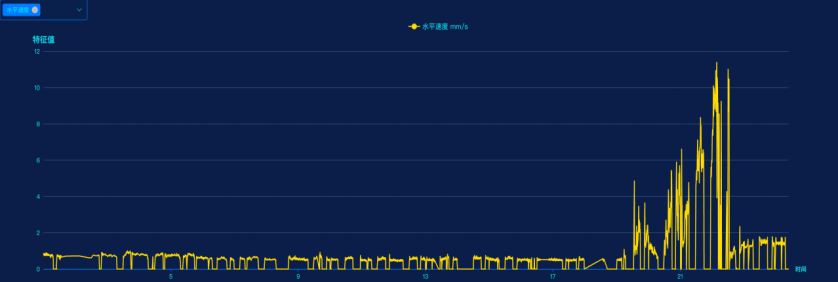
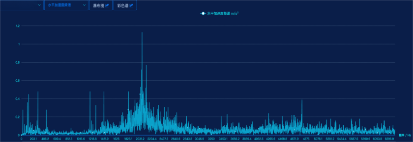
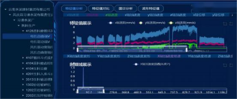
The vibration trend is increasing rapidly, and the acceleration spectrum shows peaks primarily at 37.5 Hz and 50 Hz. This does not align with the normal pattern.
Motor free-end vibration trend
Vibration Trend at the Motor Drive End
3. Diagnosis Conclusion and Recommendations
After systematic diagnostic analysis: The equipment exhibits coupling wear or misalignment. Currently, the equipment is operational and can be monitored; this provides an opportunity to inspect the coupling for wear and assess any misalignment in the equipment.
4. User Maintenance Confirmation
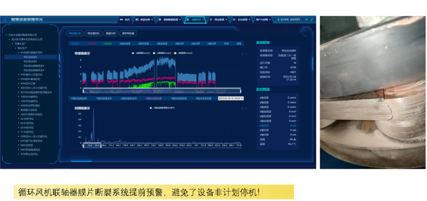
On March 16, the user conducted an on-site inspection and discovered that the coupling diaphragm had fractured. After maintenance and replacement, the fan vibration decreased from the original 9.16 mm/s to 4.03 mm/s, and the vibration frequency of 37.5 Hz completely disappeared, with vibration trends now stable.
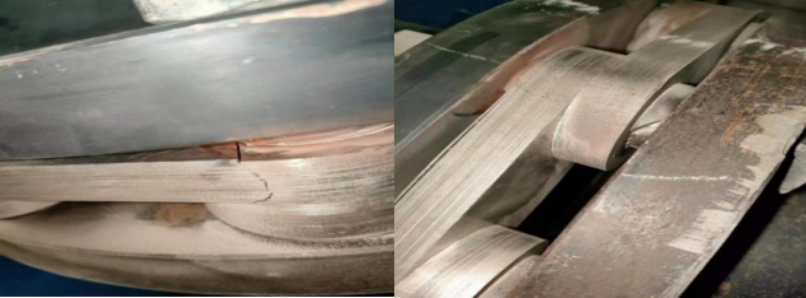
Coupling diaphragm fracture
Vibration Trend of the Motor Free End After Maintenance
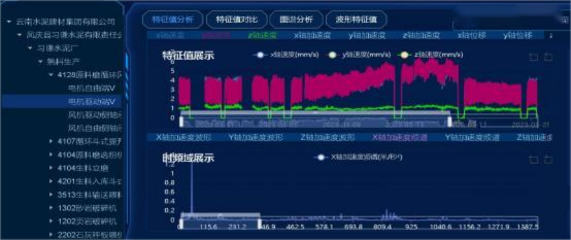
Vibration Trend at the Motor Drive End After Maintenance
5. Post-event feedback recognition
Related news
Make industry smarter and equipment healthier

Service Hotline
+86-27-6349 9950
Contact Information
Email: administrator@hbicc.com
Address: No. 6, Fozulingle Third Road, East Lake High-tech Development Zone, Wuhan, Hubei Province