
IEP3000-4
Multi-channel Analog Signal Acquisition Terminal
Category:
The IEP3000-4 series is an industrial-grade standard 4mA~20mA acquisition terminal with eight differential input channels, featuring a high acquisition accuracy of up to 24 bits. The AD acquisition section uses optoelectronic isolation, providing strong anti-interference capability, suitable for complex industrial site environments. This acquisition terminal supports wireless WiFi, LoRa, and wired RS485 communication methods, meeting various application scenarios in industrial sites and information technology.
Contact:
Design characteristics
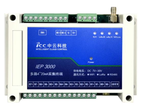
· 8 channels of standard 4mA~20mA or 0V~10V analog signal acquisition with bipolar input and strong common-mode rejection capability
· Uses 24-bit high-precision ADC conversion chip, sampling accuracy 0.1%, sampling frequency ≤10Hz
· WiFi wireless remote transmission method, outdoor unobstructed transmission distance up to 300 meters
· LoRa wireless remote transmission method, outdoor unobstructed transmission distance up to 3000 meters
· RS485 communication interface with communication distance less than 1000 meters, transmission distance can be increased through repeaters
Product Advantages
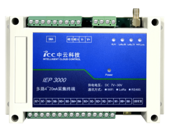
· Modbus-RTU protocol compatible with various configuration and PLC systems
· Wide voltage power supply, power range +7V to +30V DC, power interface with built-in reverse polarity protection and overvoltage protection
· Input channels and AD input interfaces are optically isolated, suitable for complex industrial environments with strong anti-interference capability
· Plug-and-play USB configuration interface connected to host computer configuration tool for quick setup
Product Parameters
Application Topology
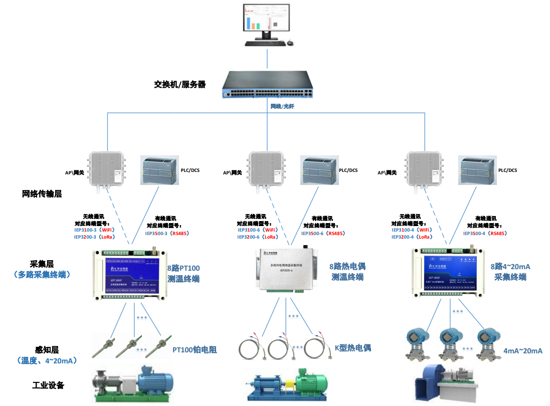
Product Specifications
| Parameters |
Performance Indicators |
| Sensor Access Method |
|
| Analog Input Types |
8 channels 4mA~20mA or 8 channels 0V~10V |
| Sensor Wiring |
Supports two-wire, three-wire, and four-wire systems |
| LoRa Communication Parameters |
|
| Operating Frequency Band |
470MHz |
| Communication Distance |
3000 meters unobstructed under ideal conditions |
| Maximum Transmit Power |
20dBm |
| WiFi Communication Parameters |
|
| Operating Frequency Band |
2402MHz-2483 MHz |
| Communication Distance |
300 meters unobstructed under ideal conditions |
| Maximum Transmit Power |
20dBm |
| RS485 Communication Parameters |
|
| Communication Protocol |
Modbus-RTU protocol, compatible with PLC, etc. |
| Communication Distance |
Less than 1000 meters |
| Environmental Parameters |
|
| Operating Temperature |
-40 ºC to +85ºC |
| Storage Temperature |
-40 ºC to +125ºC |
| Relative Humidity |
95% (non-condensing) |
| Power Supply Parameters |
|
| Power Supply Range |
DC 7V~30V |
| Power Consumption |
Less than 10W |
| Appearance Parameters |
|
| Enclosure |
Plastic flame-retardant enclosure, IP30 |
| Dimensions |
145mm x 90mm x 40mm (excluding antenna) |
| Weight |
Approximately 300g |
| Other Interfaces |
|
| USB Interface (for configuring terminal parameters) |
Connects to upper computer configuration tool for setup |
| Antenna Interface (SMA connection) |
470MHz LoRa antenna or 2.4GHz WiFi antenna |
Interface Signal Definition Description
Interface Signal Definition Description
| Interface Number |
Interface Definition |
Remarks |
| V+ |
Power Supply Positive Pole |
|
| V- |
Power Supply Negative Pole |
|
| RS485_A |
RS485 Positive Pole |
|
| RS485_B |
RS485 Negative Pole |
|
| IN0+ |
First channel analog input positive terminal |
|
| IN0- |
First channel analog input negative terminal |
|
| IN1+ |
Second channel analog input positive terminal |
|
| IN1- |
Second channel analog input negative terminal |
|
| IN2+ |
Third channel analog input positive terminal |
|
| IN2- |
Third channel analog input negative terminal |
|
| IN3+ |
Fourth channel analog input positive terminal |
|
| IN3- |
Fourth channel analog input negative terminal |
|
| IN4+ |
Fifth channel analog input positive terminal |
|
| IN4- |
Fifth channel analog input negative terminal |
|
| IN5+ |
Sixth channel analog input positive terminal |
|
| IN5- |
Sixth channel analog input negative terminal |
|
| IN6+ |
Seventh channel analog input positive terminal |
|
| IN6- |
Seventh channel analog input negative terminal |
|
| IN7+ |
Eighth channel analog input positive terminal |
|
| IN7- |
Eighth channel analog input negative terminal |
|
Input Signal Wiring Diagram Definition Description
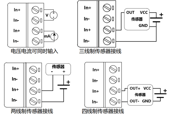
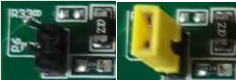
Note: 1. When Inx measures voltage signals, the corresponding channel jumper Px is disconnected, as shown in the left figure below;
2. When Inx measures current signals, the corresponding channel jumper Px is connected, as shown in the right figure below;
Antenna Installation Instructions
The antenna interface of the single-channel edge intelligent terminal is an SMA female socket. Screw the SMA male connector of the matching antenna onto the sensor acquisition edge terminal antenna interface and ensure it is tightened to avoid affecting signal quality.
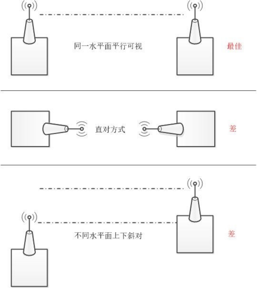
Antenna placement guidelines are as follows:
(1) Keep as far away as possible from large metal planes and the ground;
(2) Ensure the antenna has a clear line of sight as much as possible;
(3) Minimize obstacles between antennas;
(4) Minimize the feed length between the antenna and the module.
The effects of different antenna installation methods are shown in the figure below.
Indicator Light Description
The IEP3000-4 series multi-channel 4mA~20mA terminals are typically used in complex external environments. To adapt to complex application environments and improve system operational stability, the IEP3000-4 multi-channel 4mA~20mA terminals adopt advanced power supply technology. Users can power the terminal using the standard configured 12VDC/1A power adapter, or directly supply the acquisition terminal with a DC power source of 7V~30V. When users supply power externally to the acquisition terminal, the power supply must be stable (ripple less than 300mV, and ensure instantaneous voltage does not exceed 30V), and the power must be greater than 10W. The 4mA~20mA terminal provides four indicator lights: "Power", "WiFi_Link", "LoRa_TX", and "LoRa_RX". The indicator statuses are as follows:
Indicator Light Status Description
| Indicator Light |
Status |
Description |
| Power |
Off |
Device not powered |
| On |
Device power normal |
|
| WiFi_Link |
Off |
Connected to WiFi |
| Blinking |
Not connected to WiFi |
|
| LoRa_TX |
Off |
LoRa mode not transmitting data |
| Blinking |
LoRa mode transmitting data |
|
| LoRa_RX |
Off |
LoRa mode not receiving data |
| Blinking |
LoRa mode receiving data |
Product Dimensions

Series Model Guide
| IEP |
3 |
1 |
00 |
- |
4 |
| Basic Model |
Channel Type |
Communication Method |
Explosion-proof Certification |
- |
Sensor Type |
| IEP |
2= Single Channel |
1= WIFI |
01= Explosion-proof Type |
- |
1= Temperature, Vibration, and Sound Three-in-One Sensor |
|
|
3= Multi-channel Analog or Temperature |
2= LoRa |
00= Basic Type |
|
2= Three-phase Current |
|
|
4= 4 Channels |
5= RS485 |
|
|
3= PT100 |
|
|
5= 8-channel Piezoelectric |
|
|
|
4= 4-channel 4-20mA Input |
|
|
6= 16-channel Piezoelectric |
|
|
|
6= 8-channel Thermocouple |
|
|
8= High Performance |
|
|
|
|
Series Model Information
| Product Model |
Product Parameter Description |
| IEP3100-4 |
Analog Signal Acquisition Terminal, WiFi Communication, 8-channel PT100 |
| IEP3200-4 |
Analog Signal Acquisition Terminal, LoRa Communication, 8-channel PT100 |
| IEP3500-4 |
Analog Signal Acquisition Terminal, RS485 Communication, 8-channel PT100 |
Material Download
Recommended products

SL1000AT-10-LF
SL1000AT-80
SL3000-X
SL4000-X
Leave a message
We will contact you as soon as we receive your information and give you a surprise.
Service Hotline
+86 27-6349 9950
Contact Information
Email: administrator@hbicc.com
Address: No. 6, Fozulingle Third Road, East Lake High-tech Development Zone, Wuhan, Hubei Province
