
GZW80/165
Intrinsically Safe Vibration Temperature Sensor for Mining
Category:
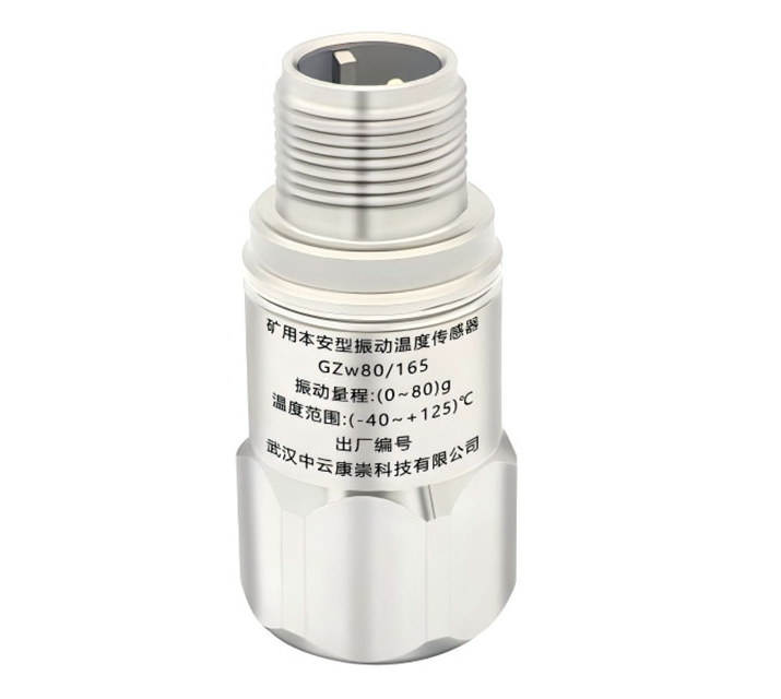
The GZW80/165 intrinsically safe vibration and temperature sensor for mining, designed and manufactured by our company (hereinafter referred to as the sensor), is a product integrating dual functions of vibration and temperature. It features a wide frequency response, high accuracy, strong anti-interference capability, good airtightness, and long service life. It is the best matching product for vibration and temperature signal measurement and monitoring systems with mining explosion-proof requirements. This product is only suitable for measuring temperature and dynamic vibration acceleration.
Contact:
Design characteristics
·Altitude not exceeding 2000m
·Ambient temperature: 0℃ to +40℃
·Ambient air relative humidity: not more than 95% (+25℃)
·Atmospheric pressure: 80kPa to 106kPa
·In hazardous locations with explosive mixtures of methane and coal dust gases
·Locations free of steam or corrosive gases that damage metal and insulating materials
·Locations free of dripping water
Product Advantages

· Integrated vibration and temperature dual functions
· Wide frequency response, high accuracy
· Strong anti-interference ability, good airtightness
· Long service life
· Explosion-proof function
Product Parameters
Electrical Performance Parameters
| Specification List | Test Conditions 25℃, 24Vdc 4mA@160Hz | ||
| Parameter List | Specification | Unit | |
| Vibration Performance | |||
| Measurement Range | 80 | g | |
| Output Signal | 0~8000 | mV | |
| Vibration Measurement Error | ±8 | % of True Value | |
| Temperature Sensor Parameters | |||
| Temperature Measurement Range | -40~125 | ℃ | |
| 0℃ Output Voltage | 500 | mV | |
| Sensitivity | 10 | mV/℃ | |
| Temperature Measurement Error | ±5 | ℃ | |
| Output Voltage Range | 100~1750 | mV | |
| Electrical Characteristics | |||
| Excitation Voltage | 18~25 (Type 24) | Vdc | |
| Constant Current Source Current | 2~10 (Type 4) | mA | |
| Bias Voltage | 12±2 | Vdc | |
| Output Impedance | <100 | Ω | |
| Insulation Resistance Between Housing and Live Circuit (@100Vdc) | >100 | MΩ | |
| Power Frequency Withstand Voltage (Housing and Live Circuit) | 1000 | Vac | |
| Broadband Noise (RMS) | ≤100 | μV | |
| Operating Environment | |||
| Operating Temperature Range | 0~40 | ℃ | |
| Shock Limit | 5000 | g | |
| Protection Level | IP67 |
| |
| Material Parameters | |||
| Sealing Method | Laser Welding |
| |
| Housing Material | 316L Stainless Steel |
| |
| Sensitive Material and Method | Piezoelectric Ceramic Shear |
| |
| Electrical Output Method | 3-pin MIL-C-5015 |
| |
| Shielding and Isolation | Internal Shielding, Isolation |
| |
| Weight | 85 | gram | |
| Accessories | |||
| Adapter Bolt | 1/4-28 to M6 |
| |
Transport Conditions
· Temperature: -40℃ to +60℃;
· Humidity: 95% (+40℃);
· Vibration: 50m/s 2;
· Shock: 500m/s 2。
Installation Technology and Electrical Connection Technology
1 Sensor Body Installation
First, install the sensor before use. Select a suitable measurement point on the tested equipment. At the measurement point, there should be a smooth flat surface with at least φ24 diameter for sensor installation. To ensure accurate vibration acceleration data and ease of use, the sensor should be firmly installed according to the sensitive direction. The recommended tightening installation methods are prioritized as follows.
1.1 Screw Installation Method
The bottom surface of the sensor should be kept smooth. Between the sensor and the tested object, it is best to apply a layer of grease or wax oil to increase contact stiffness, then tighten with nominal screws to obtain the sensor's calibrated frequency response characteristics.
Screw installation: Recommended tightening torque is 3Nm.
1.2 Adhesive Installation Method
When drilling holes on the tested object is not allowed, adhesives approved by the equipment owner can be used, such as "502", Loctite "454" quick-drying glue, or others like epoxy resin glue, double-sided adhesive tape, etc. Adhesive installation affects the sensor's frequency and amplitude characteristics and may sometimes cause unacceptable measurement errors. Adhesive installation is sensitive to temperature changes and should be carefully selected based on actual engineering conditions.
1.3 Magnetic Base Method
The magnetic base installation method lowers the upper frequency response limit and causes abnormal low-frequency response of the vibration acceleration sensor. It should be used cautiously. The measurement range is easily limited by this method, and the magnetic force is greatly affected by temperature. After reaching a certain temperature, the magnetic pole capability rapidly degrades. Please be aware and choose carefully.
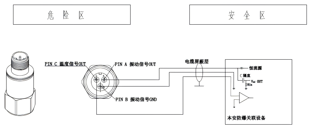
2 Electrical Connection Technology
This product's vibration part is a two-wire IC circuit product and must be powered by a constant current source. Direct DC power supply or other power methods are strictly prohibited, as they may damage internal components and cause no output. The correct electrical connection is shown in the figure below:
3 Cable Connection Technology
The selection of cables should comply with relevant standards. In harsh environments such as high temperature, high humidity, acid and alkali, and salt spray, cables with appropriate protection ratings should be used. If necessary, protective soft rubber should be used to fill gaps to prevent moisture, acid, alkali, and salt spray intrusion. After electrical connection of the cable, the cable should be fixed as close as possible to the sensor end. When possible, sensors should be kept away from strong acid and strong alkali environments to avoid contamination of electrical contact parts, which may affect or damage electrical connection performance.
The maximum length of the cable connecting the sensor and related equipment is 100 meters. Excessive extension of the connection length risks attenuation of the high-frequency components of vibration signals, increased temperature measurement errors, and intensified interference signals.
Cables should preferably be selected with the following parameter conditions: cable cross-sectional area ≥ 0.5 mm². 2 Distributed capacitance not greater than 0.1 μF/km; line resistance not greater than 50 Ω/km.
Material Download
Recommended products

SL1000AT-10-LF
SL1000AT-80
SL3000-X
SL4000-X
Leave a message
We will contact you as soon as we receive your information and give you a surprise.
Service Hotline
+86 27-6349 9950
Contact Information
Email: administrator@hbicc.com
Address: No. 6, Fozulingle Third Road, East Lake High-tech Development Zone, Wuhan, Hubei Province